Tuesday, August 21, 2012

Home Hazard Weather Station: V1.0 Complete!

The prototype Home Hazard Weather Station is up and running!

Top view:

Back view:

Side View 1:

Front view:

Side View 2:

Running code on the computer:

Monday, August 20, 2012

Testing

Today I start testing:
Here's a picture of everything wired up to the computer.


Immediately, I notice that the fan is not working. Although the Arduino can produce up to 5V, it can only produce up to 41 mA of current. The fan requires at least .07 Amps to operate. I will have to figure something out, or I'm left with a twitchy fan.

The gas sensors seem to work fine, though as before, they run quite hot. The Geiger Counter also works as expected, though it seems to pick up more radiation than before. I'm not sure what's causing this - perhaps there's something in another sensor that sets it off.

Other sensors don't seem to work at all. I finally figured out that it was because I soldered the connections wrong. Although the solderable breadboards I got are supposed to be like the regular bread boards, these seem to have an extra horizontal line of connected holes, unlike the bread boards I was working with. This threw me off as I was soldering, and, needless to say, I made a few mistakes.

Unfortunately, it takes a long time to re-solder everything since there's so many wires in the way, but I will finish my tomorrow and continue testing tomorrow. 

Friday, August 17, 2012

Soldering + More Assembly

Short update since it look a long time to solder everything... 

The top is done! I've soldered/attached all the sensors to it. 


Putting the top together with the base:

On Monday, I will finish up all the internal wiring and start testing.

Thursday, August 16, 2012

Assembly I

Assembly begins! 

Removable Base:
Here's the removable base with the Arduino and Geiger Counter circuit board attached. I have removed the actual tube since it will be placed on top of the box. The two black wires that I've soldered are going to connect to the tube. 

The two green one connect to 5V and GND, and the blue wire is the data wire. 


Note that you can also see the Velcro on the bottom of the base.

The Box: 
The fan is in the back. The cutout is for the Arduino's ports. Note that there is also Velcro on the bottom of the box.


There are two little flanges that act as convenient handles for the box when you want to pick it up and move. The top will also be fastened on these flanges.


Oops! The fan cutout was slightly smaller than the actual fan. But it still looks nice don't you think?

Top:
The most complicated part of the box, featuring all of the sensors and their associated circuitry. I've only managed to finish the gas sensors and attach the Geiger Counter tube, the temperature/barometric pressure sensor, and the temperature/humidity sensor.


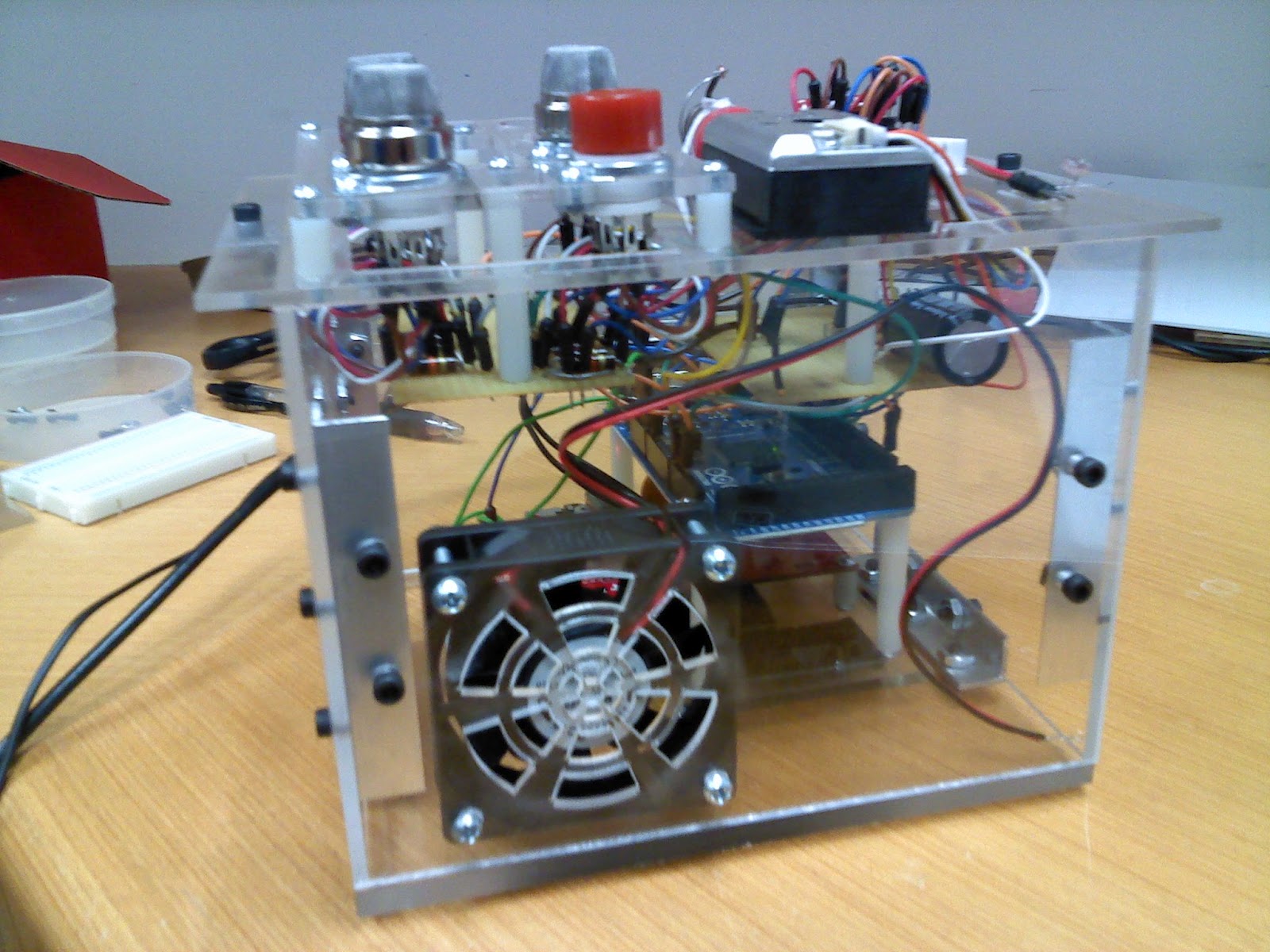
Everything together: 
It's a wireforest! In a box! No but seriously, once I figure out where everything is placed, i will trim the wires a bit shorter and use some fasteners to make things more organized. 


Tuesday, August 14, 2012

Fixing some parts

I decided to change one of the connectors to improve the design. The old connector only had one hole on the bottom, which meant that once you took off the top of the box, it could move or wobble. The new connector has two holes on the downwards facing side. This way, the connector won't move or wobble as much when you unscrew the top screw and take off the top of the box.


This meant that I would have to re-machine the walls as well, which I did:

(I messed up with one of the holes, which is why the wall piece on the right has three holes on top. But the extraneous hole will be covered by the connector anyways, so the aesthetics won't be compromised. =])

I also finished making the back wall. The rectangular cutout is for the ports on the Arduino. 

Finally, I cut out some of the L-shaped connectors:
 Tomorrow I will drill holes into them. This is the last part of my project that I have to machine, so after that, all that remains is the assembly (the fun part!). 

Friday, August 10, 2012

More Machining and Gas Sensor Setup

More machining - I finished the two walls. 

Gas Sensor Base: This was all done by the laser cutter. The second try went much better than the first because I worked with a bigger piece of Plexiglas that allowed the machine more leeway to zero imprecisely.

 After fininshing the base, I have to transfer the connections from my breadboard to my solderable breadboard that I machined a few days earlier. The solderable board has the same wiring as my breadboard, so it is easy to transfer connections.
 

After soldering everything together, I have to fix the gas sensors to the base I just machined. The gas sensors go into these little 7-pin vacuum tube sockets, which then sits snugly in the little holes on the base. I then solder the wires of the gas sensors onto the solderable breadboard and screw in some standoffs to create a small unit:


This will be later attached to the top of the box, on which we will install all of the other sensors. The four free wires are the data wires that will be connected to the Arduino.

Wednesday, August 8, 2012

Machining

Made these pieces the last two days: 

Drilled holes in the circuit board - this means I can start soldering things to it now. 

Polished the edges of some of the Plexiglas walls (it still has the protective cover on it). I made the holes too small at first so I went back and redid them. 

Before and after: 

Finished machining the base:

Lasercut the gas sensor base. As you can see, the cutting is off so I will have to redo this. It's actually still usable, but laser cutting is fast so it's not a huge problem to remake this.